Electronic Puzzle Box
Overview
In my fall semester of my masters degree, 2021, I took ME8283: Design of Mechatronic Products. The course focused on the basics of microcontrollers, and for the capstone students were tasked with using the PIC 16F18446 to be the logic in a device of their own design. In groups of two, my groupmate and I chose to make a puzzle box!
The project itself was very open ended, allowing students to use whatever sensors they wanted, and whatever mechanical and electrical designs they could make. Firmware was also very open ended, so long as all of the software was written by the students or taken from the Microchip libraries included with the PIC MCU. This put the Arduino IDE and Arduino libraries strictly off-limits.
Device Description:
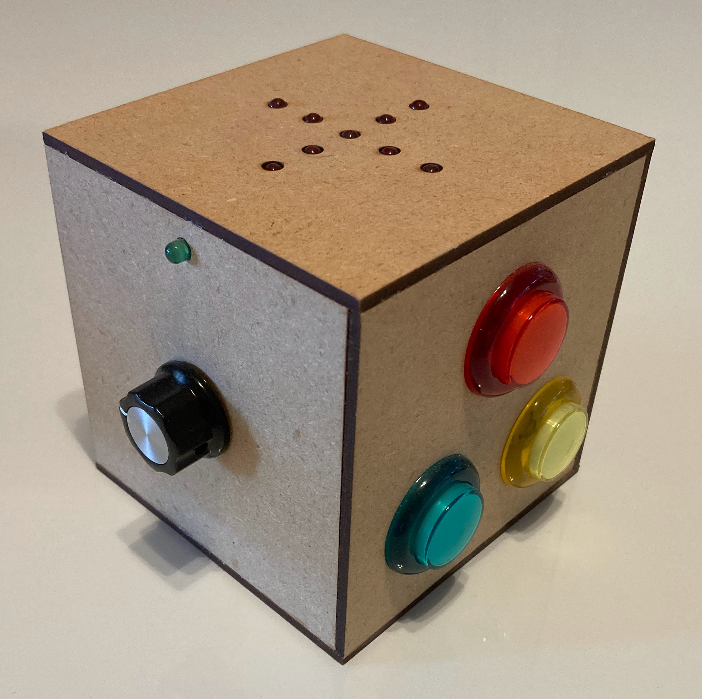
The device was an interactive puzzle box for a player to solve. On the top of the box was a series of LEDs laid out in a cross shaped pattern. The puzzle box challenged the player to balance the box about a certain axis while simultaneously turning knobs and pressing buttons in a proper order. Each playthrough of the box, the correct orientation and positioning of the box and knobs was randomly generated, allowing players to play multiple times without repeating what they did in previous games. The goal was to update the age old concept of a puzzle box using contemporary technology.
Technology
The puzzle box contained a three axis accelerometer that measured the relative angle of the box. The box randomly generated the desired z-axis orientation on each playthrough, using the accelerometer’s initial output to generate the seed. The high precision of the accelerometer ensured that the seed was essentially random, as even placing the box on a perfectly still surface would still result in wide variations in the least significant bits of the accelerometer. To align the box with the desired z-axis orientation, the player had to tilt the box until the x and y axes, were orthogonal to the desired z-axis.
Feedback on orientation was provided to the player using the array of 10 LEDs on the top. The LEDs were arranged in an X pattern. When the box was aligned the center LED would light. All other times, LEDs on the arms of the X would light, with their distance from the center indicating how far out of alignment the box was. Using the PIC 16F18446 enforced a strict upper limit on how many IO pins were available, and the LED array posed a challenge. To light each LED on command, a technique called Charlieplexing was used, allowing 10 LEDs to be controlled with only four pins by using the tri-state nature of each pin (high, low, impedance).
Simultaneously, the player had to turn on three lights with buttons on the front of the box. Some of these lights may already have been lit and would turn off if the button was pressed again. Two more lights also needed to be turned on, one on each side. One was controlled by a linear potentiometer, and the other a rotary potentiometer. Like the box orientation and the buttons, the correct location of each potentiometer was set randomly by the microcontroller on each playthrough.
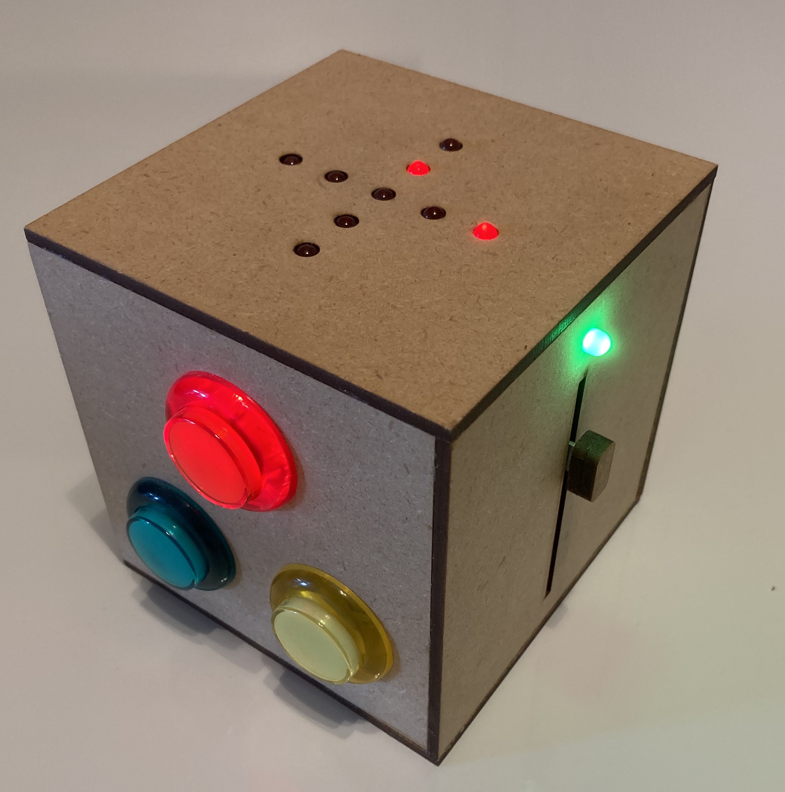
A complete playthrough of the box consisted of 10 consecutive rounds. The player was given 10 seconds to complete the first round, nine for the second, and so on down to just one second to complete the 10th round (a challenge that only one player has accomplished to date). Once the 10th round was completed, or more realistically when the player failed to complete a round, the LED array on the top of the box would flash, then their score would be shown, represented by the appropriate number of LEDs lighting up on the top of the box.
Manufacturing
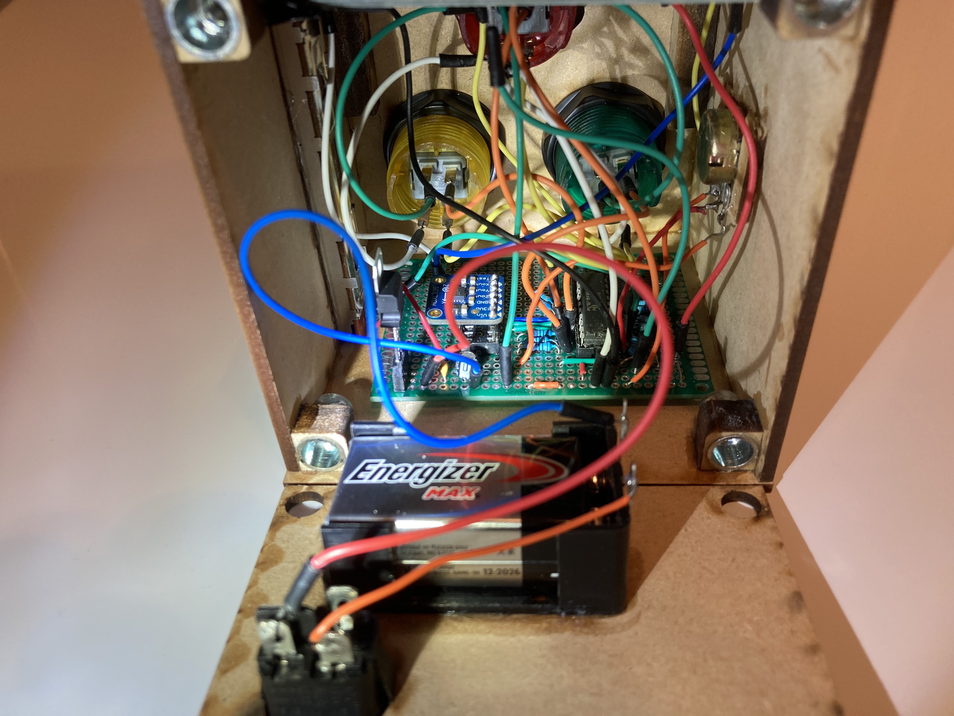
The walls of the box were made from lasercut MDF, with five sides glued together and the back panel that contained the battery bolted on using threaded inserts glued into the box. The MCU, accelerometer, and power regulating components were all soldered onto a PCB prototyping board. The array of LEDs was soldered onto a separate board, and it and the other LEDs, buttons, and potentiometers were wired to the main board. The wiring was not as clean as it could have been, but serviceable, especially considering this was my first time wiring and soldering.
Technical Challenges:
The first challenge faced, and the one that took by far the most time, was getting the accelerometer to communicate with the microcontroller. Initially, the goal was to use I2C, but the Microchip approved I2C library was not able to connect with the accelerometer, and after two weeks of troubleshooting and no communication, the decision was made to use a different accelerometer that used SPI. This decision was resisted initially despite the tight timelines because I2C requires two pins while SPI requires three. However, the implementation of Charlieplexing saved enough pins to enable the switch, with the Microcontroller’s SPI library having no issues communicating with the new accelerometer.
Charlieplexing was another challenge initially, though the real challenge came from ensuring the mapping was accurate before soldering. Compared to simply wiring each LED directly to a pin, Charlieplexing requires much more preparation, but the number of pins saved more than justified the effort.
Overall, however, the largest challenge was not technical implementation, but logistics. Pin management, purchasing and testing materials, iterating on designs, soldering and manufacturing, and time management were the real challenges. This project went from initial concept to finished demonstration piece in about two months, while also working on other university courses at the same time. Having to switch from I2C to SPI was a relatively small change, and with time either protocol would have worked. The real issue was navigating overlapping requirements and going over the time budget initially alloted to acceleromter implementation. Though this was a relatively small project, it provided an excellent window into the real-world challenges faced when a small change or shifted timeline in one part of a project can have waterfall effects that impact all downstream implementations. The most impactful decision our group made in this project was before any code was written, before any parts were purchased, before any wires were soldered. The most impactful decision was to cut down the number features from our initial designs to what we thought was truly feasible. Given how close we came to the deadline, this was a good decision.
Components
- (1) Microcontroller PIC16F18446-I/P
- (1) Adafruit ADXL335 accelerometer
- (1) Linear Potentiometer
- (1) Rotational Potentiometer
- (12) LEDs
- (3) LED Buttons